Surface Finishing AM or 3D Metal Printed Parts with Centrifugal Isotropic Finishing
- Dave Davidson

- Apr 22, 2017
- 3 min read
Updated: May 23, 2020
For additional information contact the Contributing Editor: David A. Davidson Deburring/Finishing Technologist | +1.509-563.9859 Cell and WhatsApp ddavidson@deburring-tech-group.com | dryfinish.wixsite.com/iso-finish
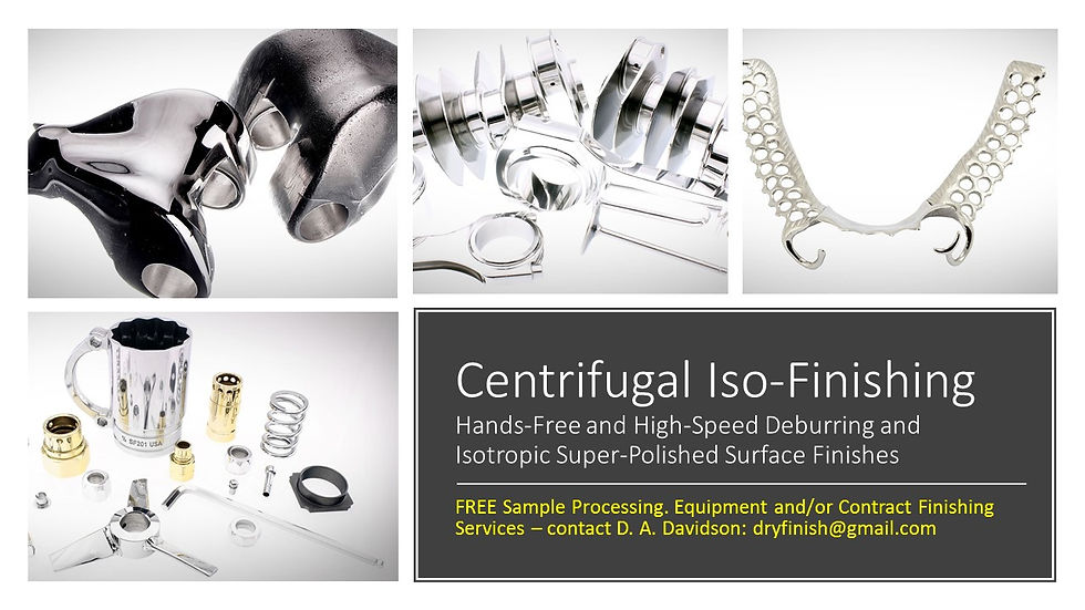

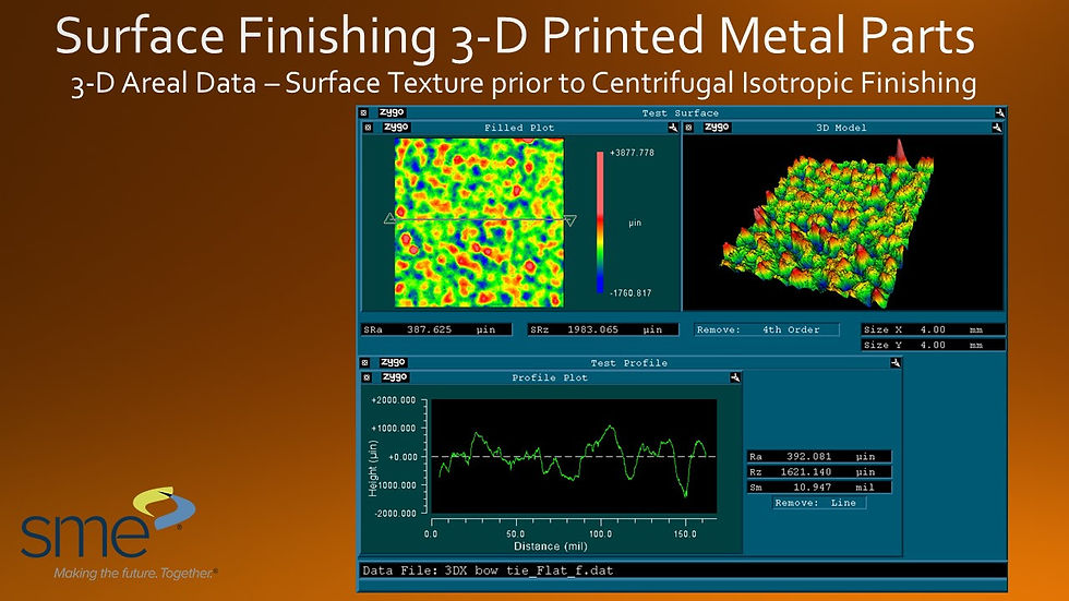
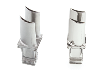
Centrifugal Isotropic Finishing has been shown to be useful in reducing the rough surfaces common to 3D printed parts. Below is an example of surface finishes that can be achieved with the method. The slides provide profilometric and areal data tabulated by Jack Clark, President of Surface Analytics. This work was performed by Jack for a study being made by SME’s Machining/Material Removal Technical Community. The slides show surface readings from a part pictured above as printed and then following centrifugal isotropic finishing. The measurements were made in both 2D and 3D. To summarize, in this test, surface roughness was reduced from 356.24µin Ra. to 12.06µin Ra.




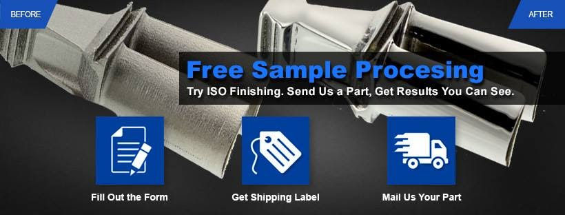
Before and after centrifugal iso-finishing. Before centrifugal iso-finish surface roughness was 350+ micro-inches Ra. After the centrifugal iso-finishing process surfaces were at 12 micro-niches Ra. See additional examples below…



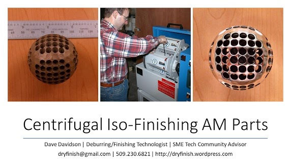
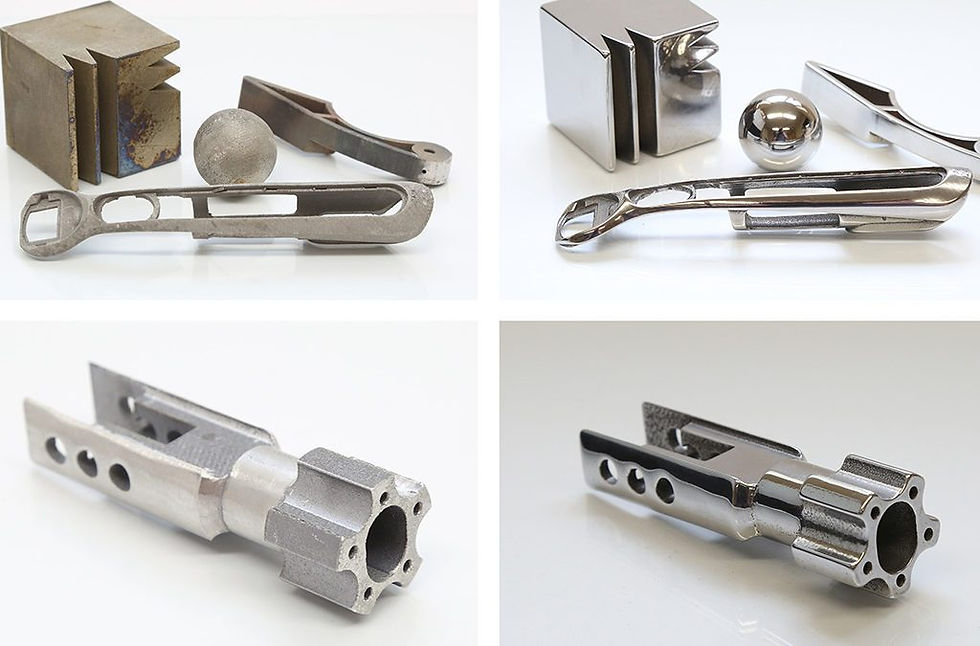


These parts were run in a centrifugal iso-burnishing process to both level surfaces and add compressive stress to parts to enhance fatigue failure resistance. Starting surface roughness was in the 350 micro-inch range. After centrifugal iso-burnishing the surface roughness was measured at 32 micro-inches Ra.
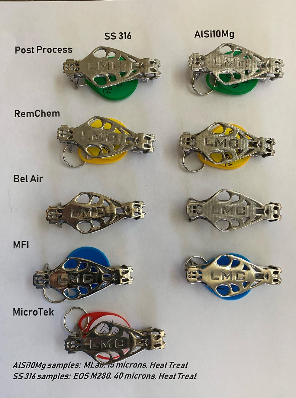
Below… ***[Technical Post]*** COMPARATIVE EVALUATION OF POST PROCESSING SURFACE FINISH on 3D PRINTED METAL PARTS (For More info: CONTACT Dave Davidson at ddavidson@deburring-tech-group.com ) In this example, the same part (built standard without optimization to address porosity or features)… was sent with the same instructions (to polish to the highest finish possible) to five surface finishing companies. The five different results are shown in the chart below The next project will be an assessment of surface finish and dimensional accuracy. Stay tuned for results. Results compiled and storyboard developed by Shannon Van Derren, President, Layered Manufacturing Consultants ***** For additional information and free sample part processing assistance for the MFI (Centrifugal Iso-Finishing) parts shown in the chart (the fourth parts on the list) CONTACT Dave Davidson at ddavidson@deburring-tech-group.com | SEE ALSO: dryfinish.wordpress.com and https://wp.me/pBEHo-XZ
Centrifugal Iso-Finishing Technology
Centrifugal isotropic finishing (CIF) is a high-energy finishing method, which has come into widespread acceptance in recent years. and a long list of important CIF applications for precision machined and additive parts have been developed in the last few years.
Similar in some respects to barrel finishing, in that a drum-type container is partially filled with media and set in motion to create a sliding action of the contents, CBF is different from other finishing methods in some significant ways. Among these are the high pressures developed in terms of media contact with parts, the unique sliding action induced by rotational and centrifugal forces, and accelerated abrading or finishing action. As is true with other high energy processes, because time cycles are much abbreviated, surface finishes can be developed in minutes, which might tie up conventional equipment for many hours.

Left: Centrifugal Barrel Finishing principles – high-intensity finishing is performed with barrels mounted on the periphery of a turret. The turret rotates providing the bulk of the centrifugal action, the barrels counter-rotate to provide the sliding abrasive action on parts.
The principle behind CIF is relatively straightforward. Opposing barrels or drums are positioned circumferentially on a turret. (Most systems have either two or four barrels mounted on the turret; some manufacturers favor a vertical and others a horizontal orientation for the turret.) As the turret rotates at high speed, the barrels are counter-rotated, creating very high G-forces or pressures, as well as considerable media sliding action within the drums. Pressures as high as 50 Gs have been claimed for some equipment. The more standard equipment types range in size from 1 ft3 (30 L) to 10 ft3, although much larger equipment has been built for some applications.
Media used in these types of processes tend to be a great deal smaller than the common sizes chosen for barrel and vibratory processes. The smaller media, in such a high-pressure environment, are capable of performing much more work than would be the case in lower energy equipment. They also enhance access to all areas of the part and contribute to the ability of the equipment to develop very fine finishes. In addition to the ability to produce meaningful surface finish effects rapidly, and to produce fine finishes, CBF has the ability to impart compressive stress into critical parts that require extended metal fatigue resistance. Small and more delicate parts can also be processed with confidence, as the unique sliding action of the process seems to hold parts in position relative to each other, and there is generally little difficulty experienced with part impingement. Dry process media can be used in certain types of equipment and is useful for light deburring, polishing, and producing very refined isotropic super-finishes.
Below: Centrifugal Isotropic Finishing Operations Videos
Need more information? Contact: Dave Davidson, Deburring/Finishing Technologist 509.563.9859 | ddavidson@deburring-tech-group.com




Comments